KDE Plasma 适合那些想要用户友好和可定制桌面的人。它是一个功能丰富且用途广泛的桌面环境,提供多种不同风格的菜单来访问应用程序。一个出色的内置界面,可以轻松访问和安装来自互联网的新主题、小部件等,也值得一提。默认情况下,KDE Plasma 很简单,它是一个干净的工作区域,供实际使用,不会妨碍您,因此用户可以创建工作流程,从而更有效地完成任务。
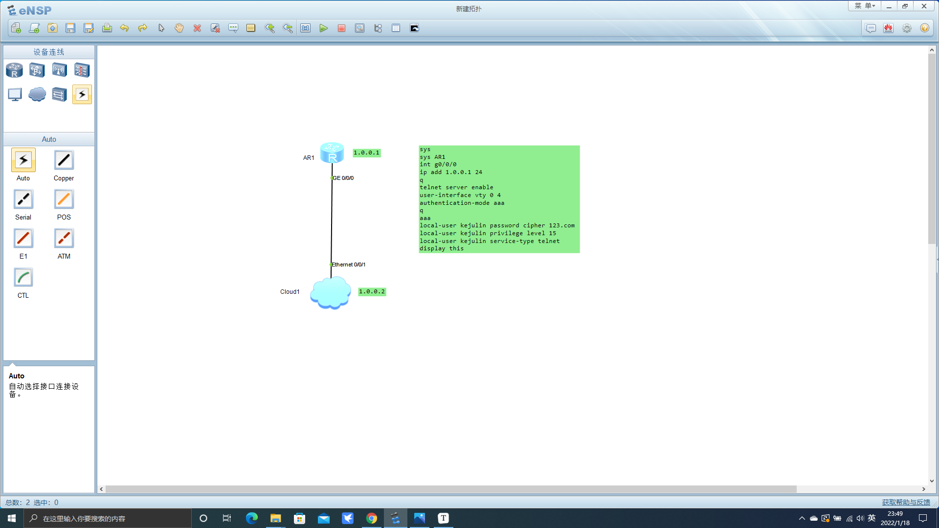
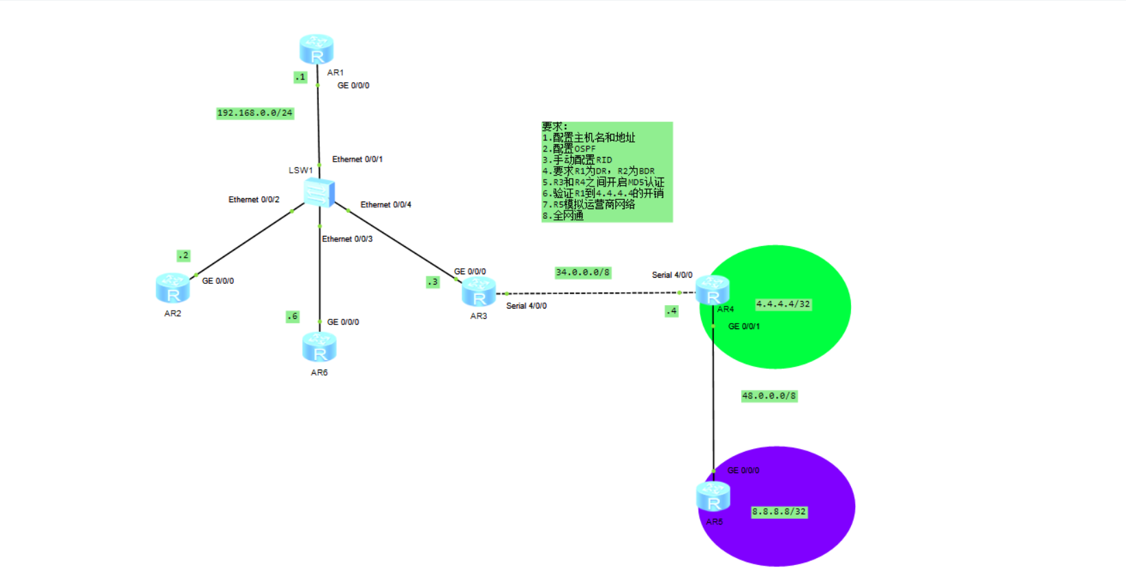
sys sys AR1 int g0/0/0 ip add 192.168.0.1 24 ospf 1 router-id 1.1.1.1 area 0 net 192.168.0.0 0.0.0.255 int g0/0/0 ospf dr-pri 200
sys sys AR2 int g0/0/0 ip add 192.168.0.2 24 ospf 1 router-id 2.2.2.2 area 0 net 192.168.0.0 0.0.0.255 int g0/0/0 ospf dr-pri 100
sys sys AR3 int g0/0/0 ip add 192.168.0.3 24 int s4/0/0 ip add 34.0.0.3 8 ospf authentication-mode md5 1 cipher julintongxue@gmail.com ospf 1 router-id 3.3.3.3 area 0 net 192.168.0.0 0.0.0.255 net 34.0.0.0 0.255.255.255
sys sys AR6 int g0/0/0 ip add 192.168.0.6 24 ospf 1 router-id 6.6.6.6 area 0 net 192.168.0.0 0.0.0.255
sys sys AR4 int g0/0/1 ip add 48.0.0.4 8 ip route-static 0.0.0.0 0 48.0.0.8 int s4/0/0 ip add 34.0.0.4 8 ospf authentication-mode md5 1 cipher julintongxue@gmail.com int lo 4 ip add 4.4.4.4 32 ospf 1 router-id 4.4.4.4 default-route-advertise area 0 net 4.4.4.4 0.0.0.0 net 34.0.0.0 0.255.255.255
sys sys AR5 int g0/0/0 ip add 48.0.0.8 8 ip route-static 0.0.0.0 0 48.0.0.4 int lo 5 ip add 8.8.8.8 32
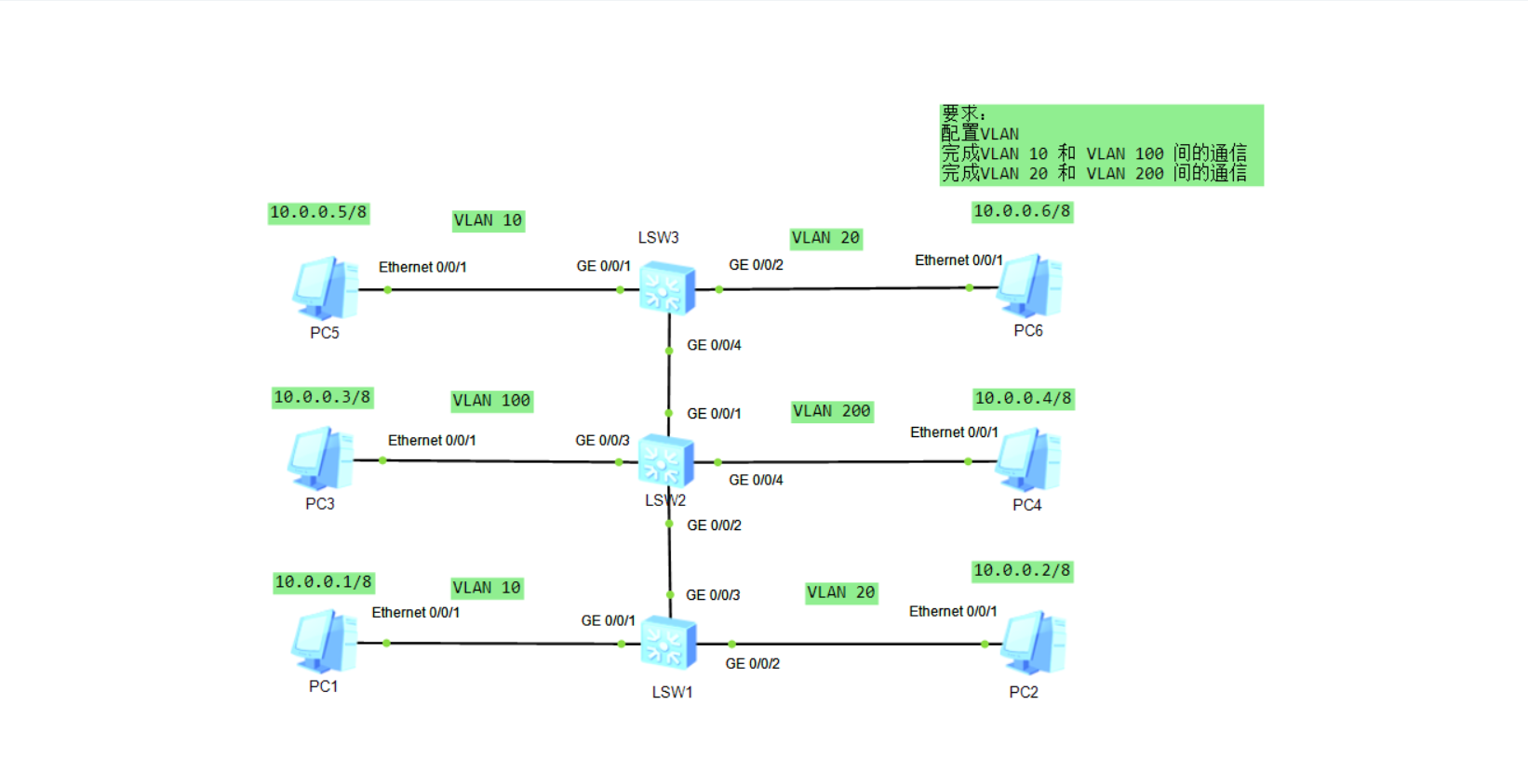
sys sys SW1 vlan batch 10 20 100 200 int g0/0/3 p l t p t a v 10 20 100 200 int g0/0/1 p l h p h un v 10 100 p h p v 10 int g0/0/2 p l h p h un v 20 200 p h p v 20
sys sys SW2 vlan batch 10 20 100 200 int g0/0/1 p l t p t a v 10 20 100 200 int g0/0/2 p l t p t a v 10 20 100 200 int g0/0/3 p l h p h un v 10 100 p h p v 100 int g0/0/4 p l h p h un v 20 200 p h p v 200
sys sys SW3 vlan batch 10 20 100 200 int g0/0/4 p l t p t a v 10 20 100 200 int g0/0/1 p l h p h un v 10 100 p h p v 10 int g0/0/2 p l h p h un v 20 200 p h p v 20
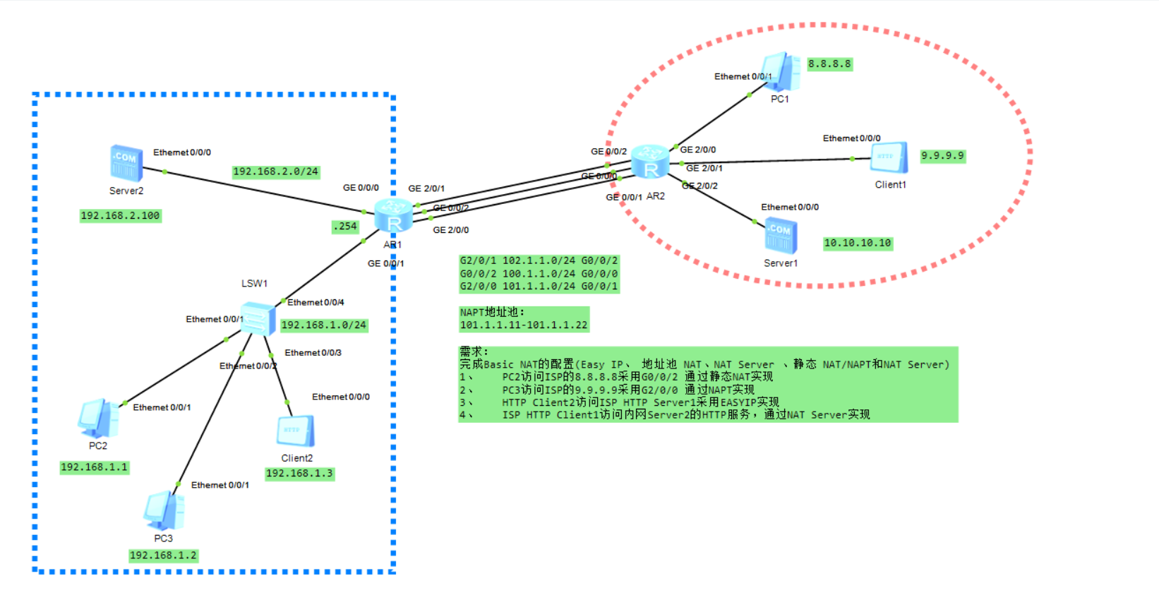
sys sys AR1 int g0/0/0 ip add 192.168.2.254 24 int g0/0/1 ip add 192.168.1.254 24 int g2/0/1 ip add 102.1.1.1 24 int g0/0/2 ip add 100.1.1.1 24 nat static enable nat static global 100.1.1.2 inside 192.168.1.1 int g2/0/0 ip add 101.1.1.1 24 ip route-static 0.0.0.0 0 100.1.1.254 ip route-static 9.9.9.9 32 101.1.1.254 ip route-static 10.10.10.10 32 102.1.1.254 nat address-group 1 101.1.1.11 101.1.1.22 acl 2000 rule permit source 192.168.1.2 0.0.0.255 int g2/0/0 nat outbound 2000 address-group 1 acl 2001 rule permit source 192.168.1.3 0 int g2/0/1 nat outbound 2001 int g2/0/1 nat server protocol tcp global current-interface www inside 192.168.2.100 www
sys sys AR2 int g2/0/0 ip add 8.8.8.254 24 int g2/0/1 ip add 9.9.9.254 24 int g2/0/2 ip add 10.10.10.254 24 int g0/0/2 ip add 102.1.1.254 24 int g0/0/0 ip add 100.1.1.254 24 int g0/0/1 ip add 101.1.1.254 24 ip route-static 100.1.1.2 32 100.1.1.1
sys sys FW1 int g0/0/0 ip add 192.168.2.1 24 service-manage all permit firewall zone dmz add int g1/0/1 int g1/0/1 ip add 172.16.1.254 24 service-manage all permit firewall zone untrust add int g1/0/3 int g1/0/3 ip add 100.1.1.1 24 service-manage all permit firewall zone trust add int g1/0/2 add int g1/0/0 int g1/0/2 ip add 192.168.2.254 24 service-manage all permit int g1/0/0 ip add 192.168.1.254 24 service-manage all permit q security-policy rule name PC1-to-200-trust-to-dmz-icmp source-zone trust destination-zone dmz source-address 192.168.1.1 32 destination-address 172.16.1.100 32 service icmp action permit q rule name 200-to-PC1-dmz-to-trust-icmp source-zone dmz destination-zone trust source-address 172.16.1.100 32 destination-address 192.168.1.1 32 service icmp action permit q rule name PC1-to-200-trust-to-dmz-icmp source-zone trust destination-zone dmz source-address 192.168.1.1 32 destination-address 172.16.1.200 32 service icmp action permit nat address-group 1 section 130.1.1.1 mode pat nat-policy rule name snat-01 source-zone trust destination-zone dmz source-address 192.168.1.1 32 destination-address 172.16.1.200 32 service icmp action source-nat address-group 1
sys sys AR1 int g0/0/0 ip add 100.1.1.254 24 int g0/0/1 ip add 8.8.8.254 24 int g0/0/2 ip add 9.9.9.254 24 int g4/0/0 ip add 10.10.10.254 24
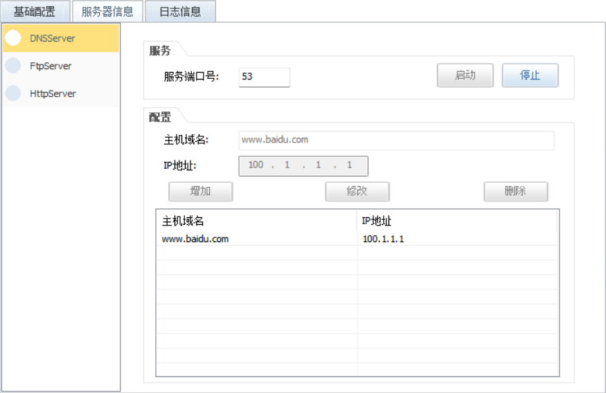
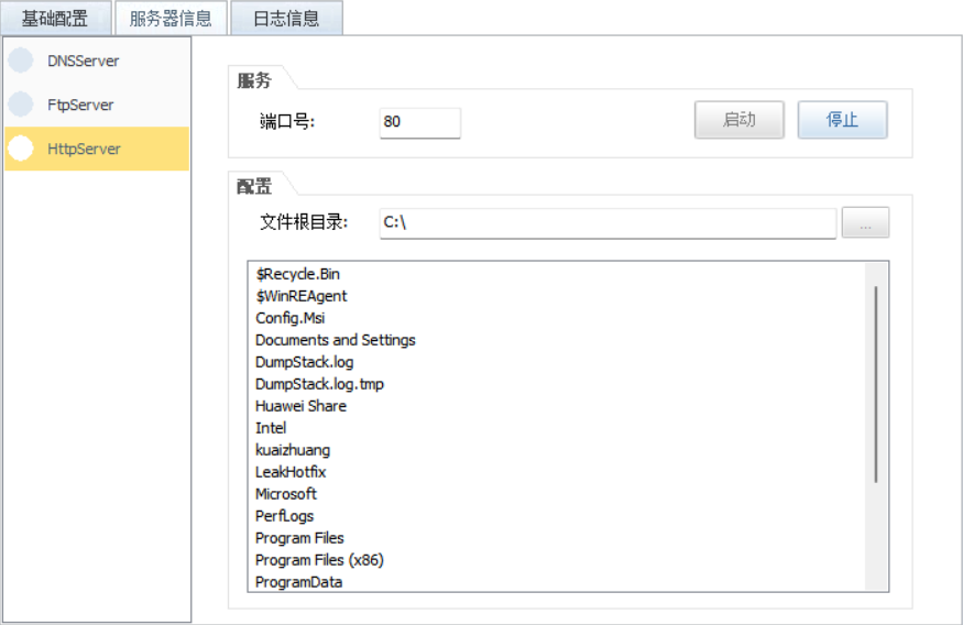
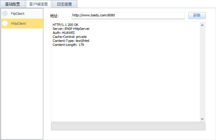
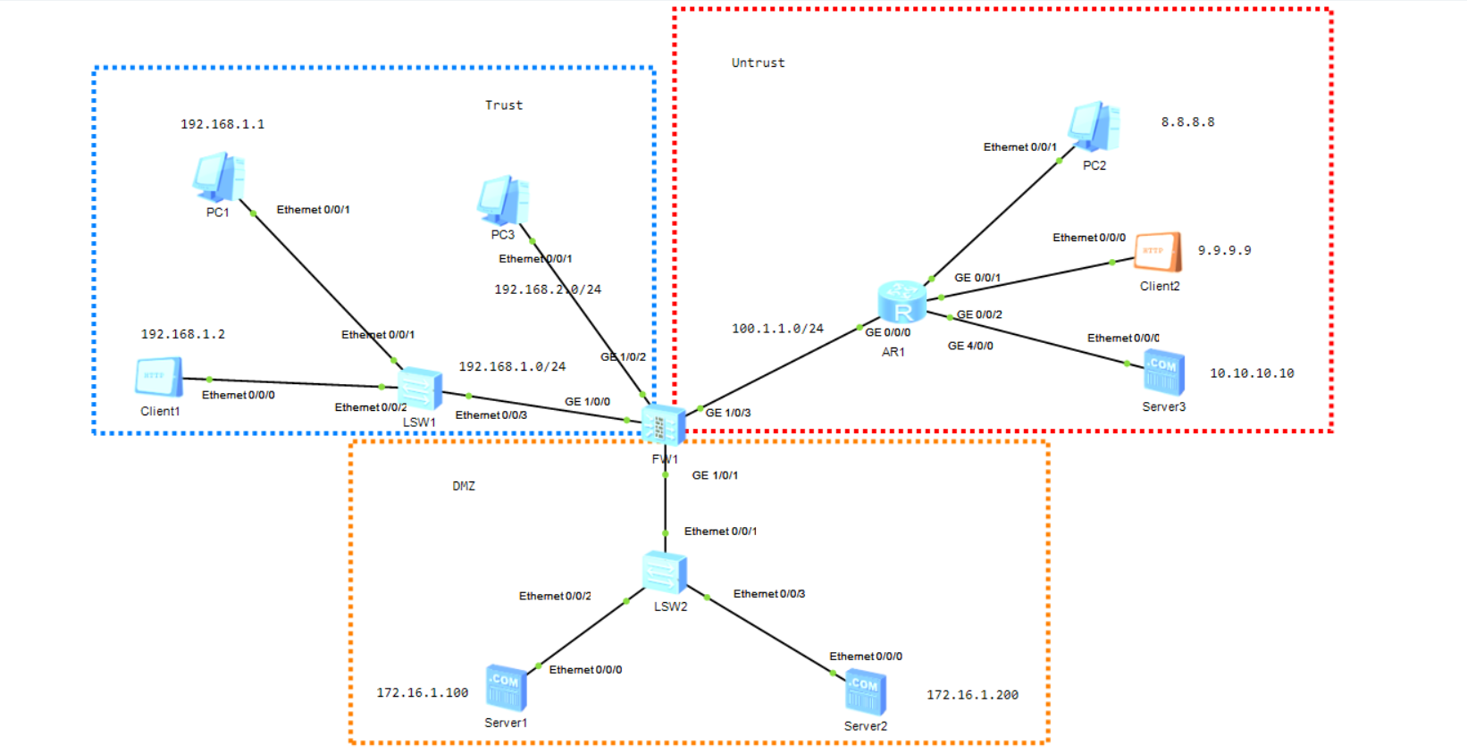
sys sys FW1 firewall zone dmz add int g1/0/1 int g1/0/1 ip add 172.16.1.254 24 service-manage all permit firewall zone untrust add int g1/0/3 int g1/0/3 ip add 100.1.1.1 24 service-manage all permit firewall zone trust add int g1/0/2 add int g1/0/0 int g1/0/2 ip add 192.168.2.254 24 service-manage all permit int g1/0/0 ip add 192.168.1.254 24 service-manage all permit q security-policy rule name PC1-PC3-to-PC2-trust-to-untrust source-zone trust destination-zone untrust source-address 192.168.1.1 32 source-address 192.168.2.1 32 destination-address 8.8.8.8 32 service icmp action permit nat-policy rule name EASYIP source-zone trust egress-interface g1/0/3 source-address 192.168.0.0 16 destination-address 8.8.8.8 32 service icmp action source-nat easy-ip q q ip route-static 0.0.0.0 0 100.1.1.254 security-policy rule name C2-to-S2-to-PC2-untrust-to-trust source-zone untrust destination-zone dmz source-address 9.9.9.9 32 destination-address 172.16.1.200 32 service dns http action permit q q nat server HTTP1 protocol tcp global 100.1.1.1 8080 inside 172.16.1.200 80 nat server DNS1 protocol udp global 100.1.1.1 53 inside 172.16.1.200 53 dns resolve dns server 172.16.1.200
sys sys AR1 int g0/0/0 ip add 100.1.1.254 24 int g0/0/1 ip add 8.8.8.254 24 int g0/0/2 ip add 9.9.9.254 24 int g4/0/0 ip add 10.10.10.254 24
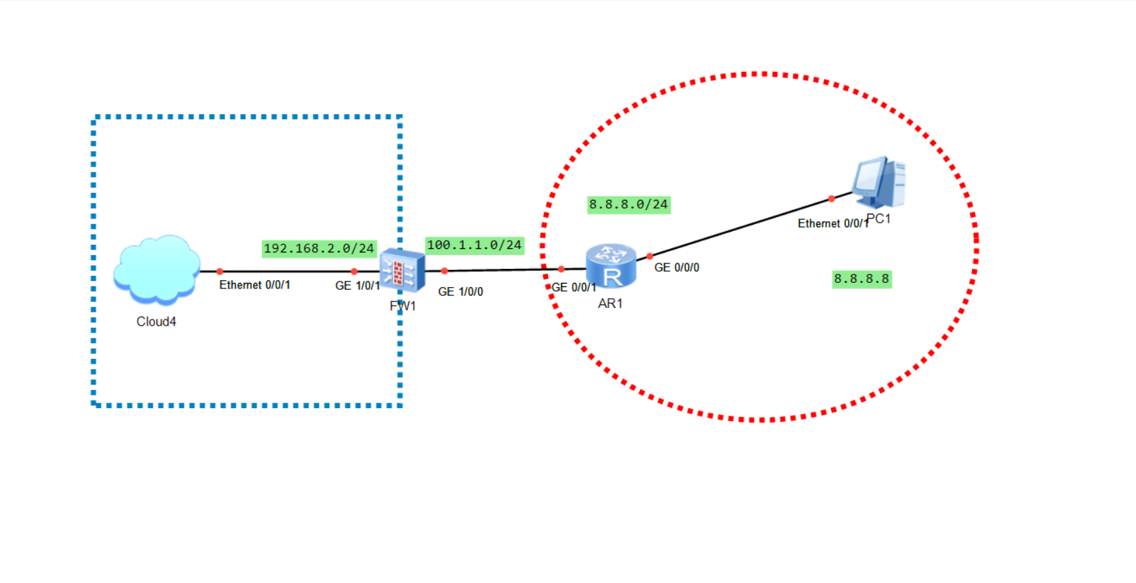
sys sys AR1 int g0/0/1 ip add 8.8.8.254 24 int g0/0/0 ip add 100.1.1.254 24 ip route-static 0.0.0.0 0 100.1.1.1
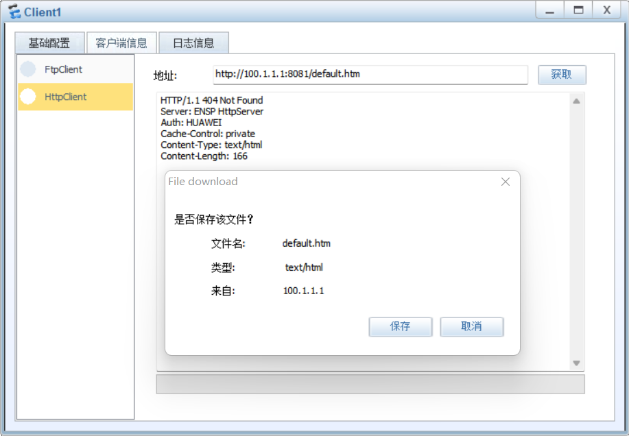
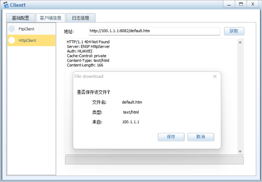
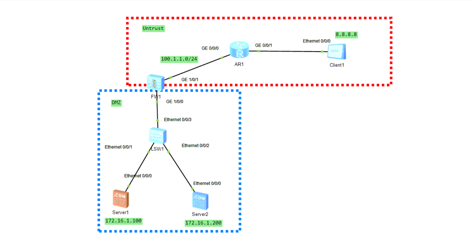
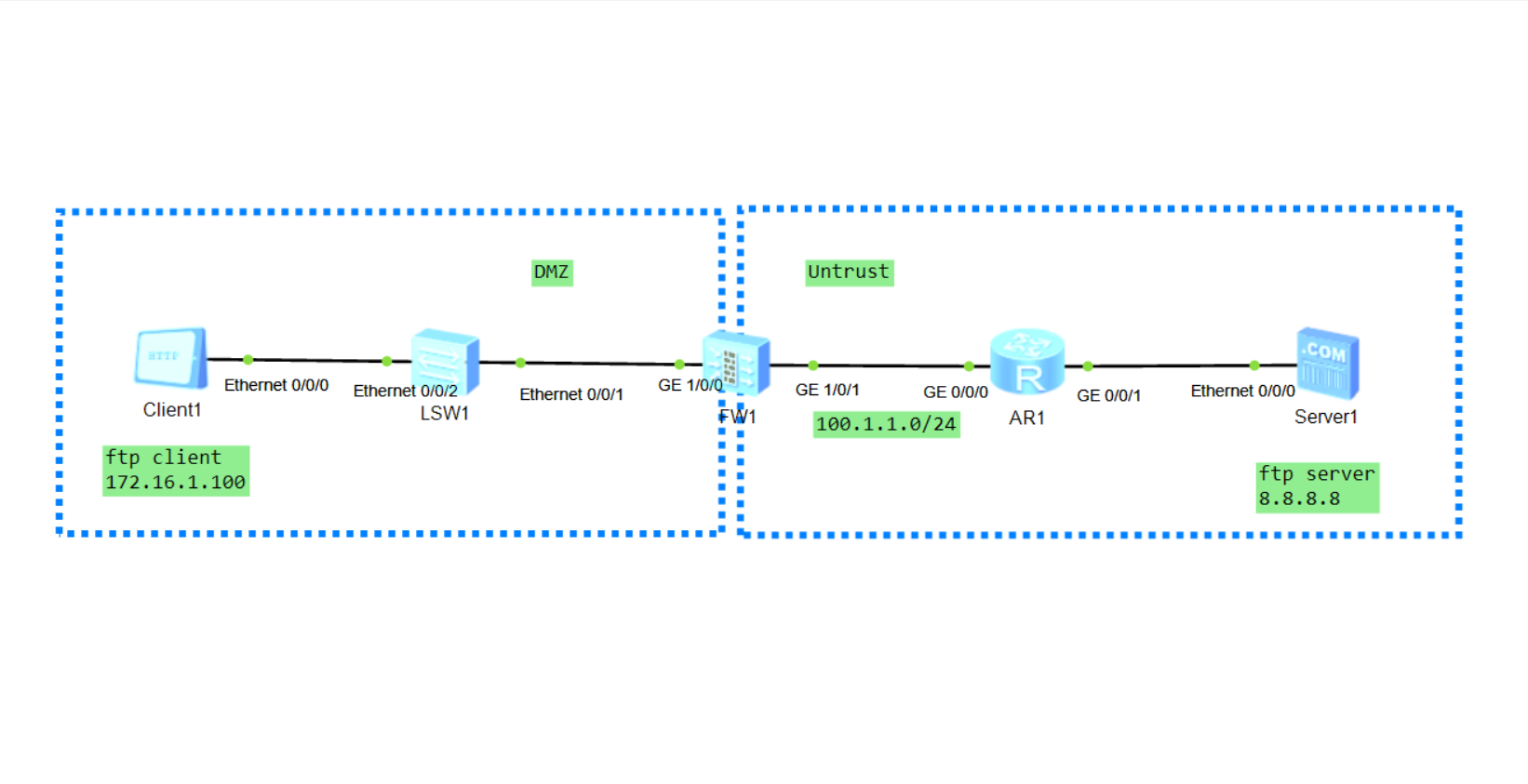
sys sys FW1 firewall zone dmz add int g1/0/0 int g1/0/0 ip add 172.16.1.254 24 service-manage all permit firewall zone untrust add int g1/0/1 int g1/0/1 ip add 100.1.1.1 24 service-manage all permit q ip route-static 0.0.0.0 0 100.1.1.254 security-policy rule name untrust-to-dmz source-zone untrust destination-zone dmz source-address 8.8.8.8 mask 255.255.255.255 destination-address 172.16.1.100 mask 255.255.255.255 destination-address 172.16.1.200 mask 255.255.255.255 service http service icmp action permit q nat server HTTP1 zone untrust protocol tcp global interface g1/0/1 8081 inside 172.16.1.100 80 nat server HTTP2 zone untrust protocol tcp global interface g1/0/1 8082 inside 172.16.1.200 80
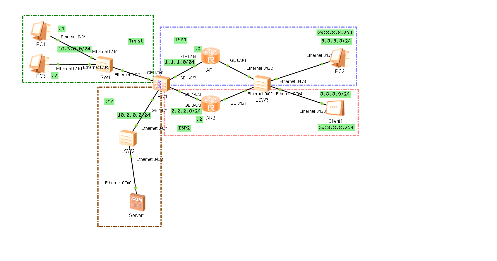
sys sys FW1 int g1/0/0 ip add 10.3.0.254 24 service-manage all permit firewall zone trust add int g1/0/0 int g1/0/2 ip add 1.1.1.1 24 service-manage all permit firewall zone name isp1 set priority 10 add int g1/0/2 int g1/0/3 ip add 2.2.2.1 24 service-manage all permit firewall zone name isp2 set priority 11 add int g1/0/3 int g1/0/1 ip add 10.2.0.254 24 service-manage all permit firewall zone dmz add int g1/0/1 ip route-static 0.0.0.0 0 1.1.1.2 pre 59 ip route-static 0.0.0.0 0 2.2.2.2 security-policy rule name trust-to-isp-icmp01 source-zone trust destination-zone isp1 destination-zone isp2 service icmp action permit nat address-group 1 route enable section 1.1.1.10 1.1.1.20 mode pat nat address-group 2 route enable section 2.2.2.10 2.2.2.20 mode pat nat-policy rule name sourcenat01 source-zone trust destination-zone isp1 source-address 10.3.0.0 mask 255.255.255.0 destination-address 8.8.8.0 mask 255.255.255.0 service icmp action source-nat address-group 1 rule name sourcenat02 source-zone trust destination-zone isp2 source-address 10.3.0.0 mask 255.255.255.0 destination-address 8.8.8.0 mask 255.255.255.0 service icmp action source-nat address-group 2 nat server HTTP1 zone isp1 protocol tcp global interface GigabitEthernet1/0/2 www inside 10.2.0.1 www nat server HTTP2 zone isp2 protocol tcp global interface GigabitEthernet1/0/3 www inside 10.2.0.1 www security-policy rule name isp-to-dmz-http01 source-zone isp1 source-zone isp2 destination-zone dmz service http action permit
sys sys AR1 int g0/0/0 ip add 1.1.1.2 24 int g0/0/1 ip add 8.8.8.252 24 vrrp vrid 1 virtual-ip 8.8.8.254 vrrp vrid 1 priority 120 vrrp vrid 1 track interface g0/0/0 reduced 30 dis vrrp brief
sys sys AR2 int g0/0/0 ip add 2.2.2.2 24 int g0/0/1 ip add 8.8.8.253 24 vrrp vrid 1 virtual-ip 8.8.8.254 dis vrrp brief
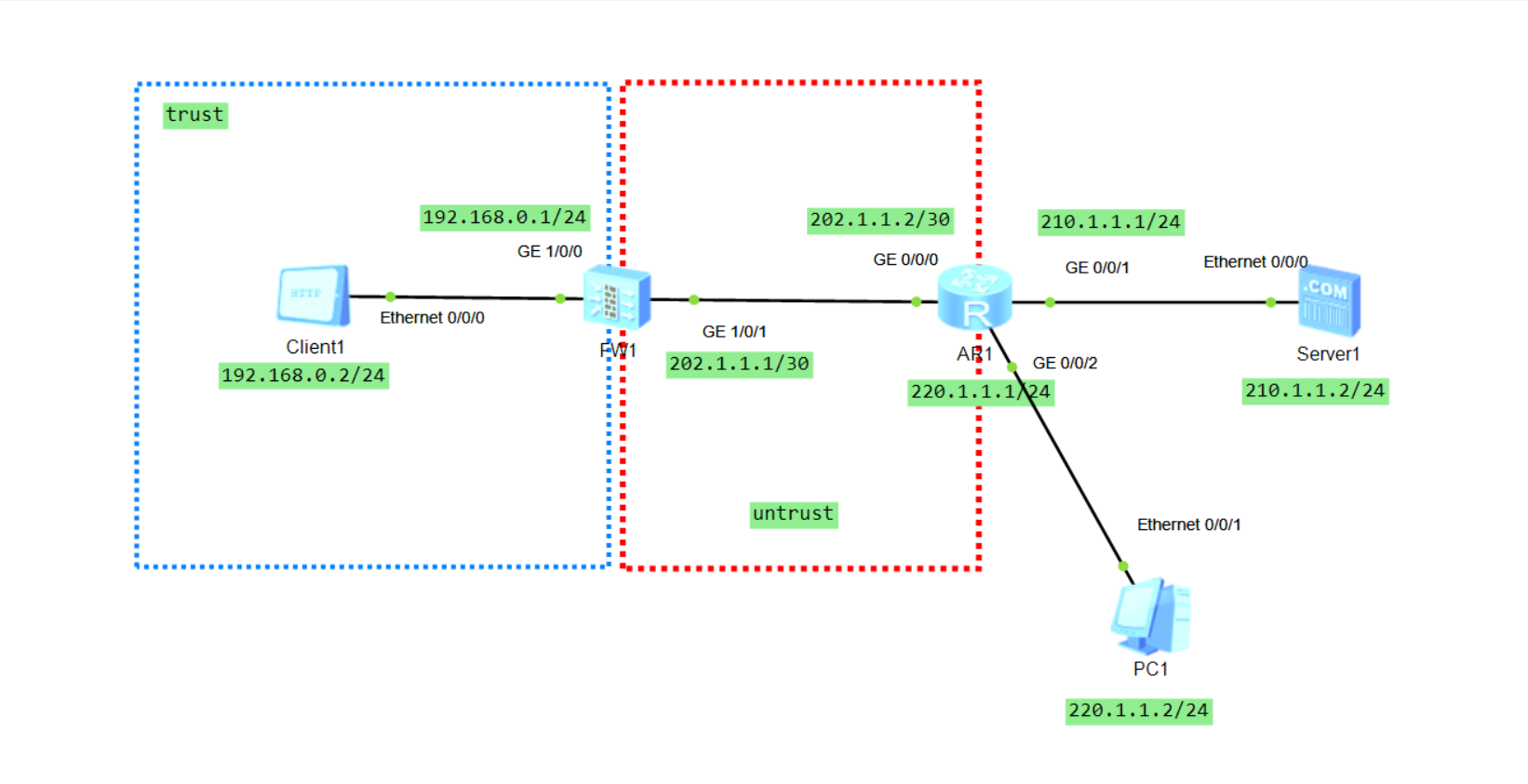
sys sys AR1 int g0/0/0 ip add 202.1.1.2 30 int g0/0/1 ip add 210.1.1.1 24 int g0/0/2 ip add 220.1.1.1 24 ip route-static 202.1.1.20 32 202.1.1.1
sys sys FW1 int g1/0/0 ip add 192.168.0.1 24 service-manage all permit int g1/0/1 ip add 202.1.1.1 30 service-manage all permit q firewall zone trust add int g1/0/0 q firewall zone untrust add int g1/0/1 q ip route-static 0.0.0.0 0 202.1.1.2 security-policy rule name trust-to-untrust source-zone trust destination-zone untrust service icmp http action permit nat address-group 1 section 202.1.1.10 202.1.1.20 route enable#这个去了就环路 mode pat nat-policy rule name sourcenat01 source-zone trust destination-zone untrust source-address 192.168.0.0 24 service icmp http action source-nat address-group 1
#上述环路是因为在AR1里面设置了一条静态路由(ip route-static),该路由的目的是让数据包有回去的方向,但是在Client1 ping 202.1.1.20 的时候,由于FW1本地没有该路由所以交给了缺省路由解决,缺省路由则会把数据交给AR1,而AR1在前面说到有了静态路由,又会把数据丢给FW1,彼此往复就形成环路。 #解决办法则是:在防火墙内设置黑洞路由,把这个会环路的路由丢黑洞里,或者route enable #dis nat-policy rule all #dis f s t v
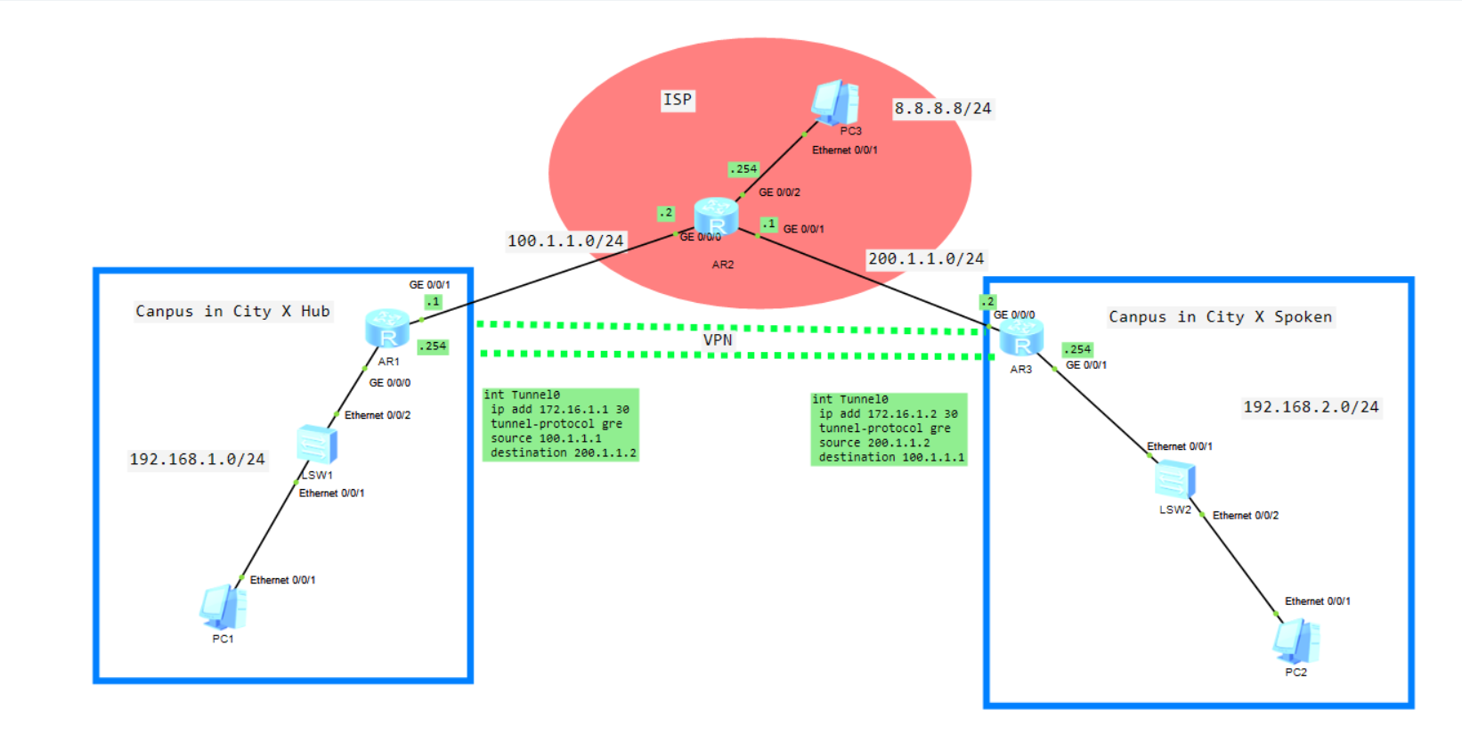
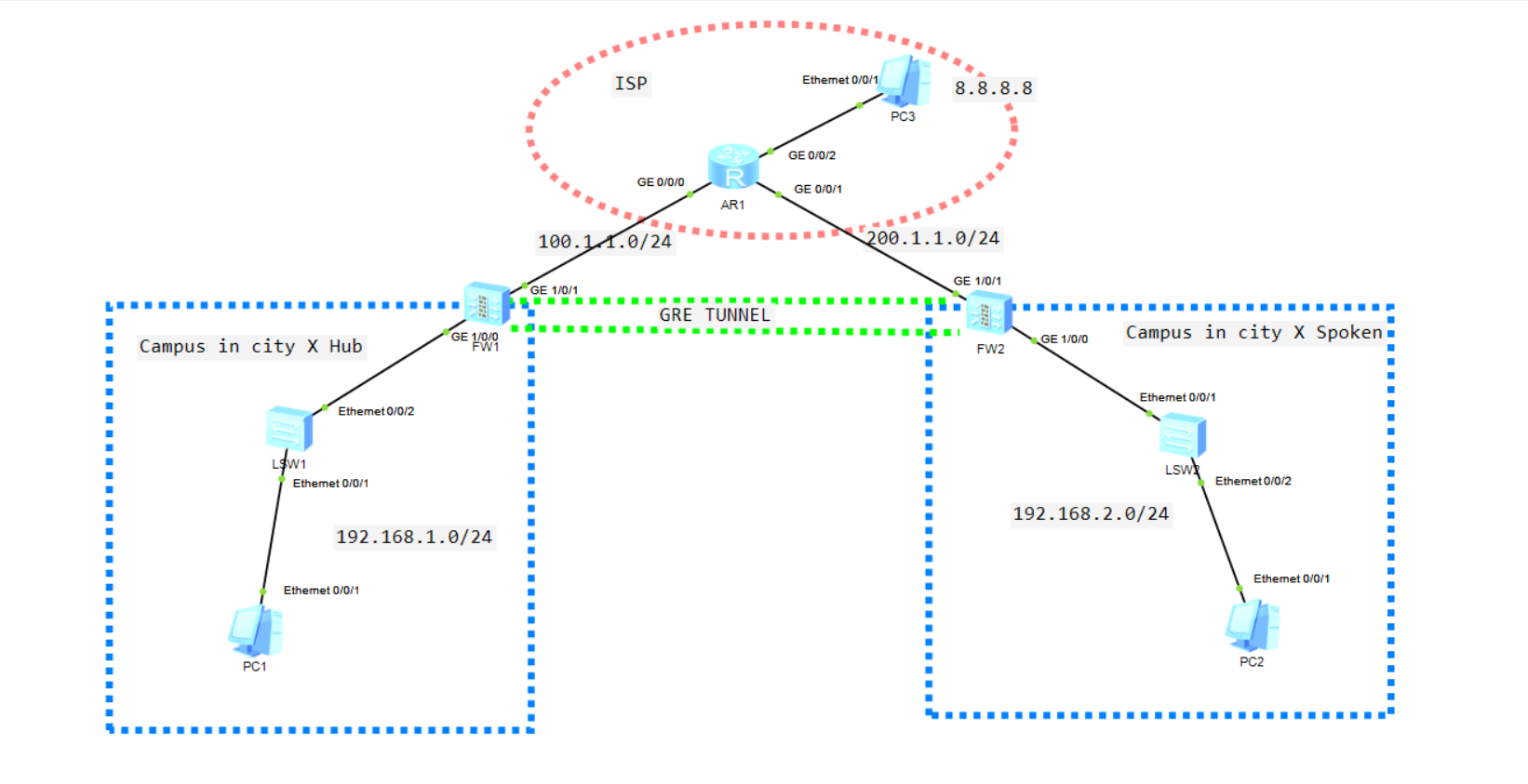
sys sys AR1 int g0/0/0 ip add 100.1.1.254 24 int g0/0/1 ip add 200.1.1.254 24 int g0/0/2 ip add 8.8.8.254 24
sys sys FW1 firewall zone trust add int g1/0/0 int g1/0/0 ip add 192.168.1.254 24 service-manage all permit firewall zone untrust add int g1/0/1 int g1/0/1 ip add 100.1.1.1 24 service-manage all permit ip route-static 0.0.0.0 0.0.0.0 100.1.1.254 security-policy rule name ISP-icmp01 source-zone local destination-zone untrust service icmp action permit rule name sourcenat01 source-zone trust destination-zone untrust service icmp action permit nat-policy rule name sourcenat01 source-zone trust egress-interface GigabitEthernet1/0/1 source-address 192.168.1.0 mask 255.255.255.0 service icmp action source-nat easy-ip int tunnel0 ip add 172.16.1.1 24 tunnel-protocol gre source 100.1.1.1 destination 200.1.1.1 firewall zone name gre set priority 10 add interface Tunnel0 security-policy default action permit ospf 1 area 0 network 172.16.1.0 0.0.0.255 network 192.168.1.0 0.0.0.255
sys sys FW2 firewall zone trust add int g1/0/0 int g1/0/0 ip add 192.168.2.254 24 service-manage all permit firewall zone untrust add int g1/0/1 int g1/0/1 ip add 200.1.1.1 24 service-manage all permit ip route-static 0.0.0.0 0.0.0.0 200.1.1.254 security-policy rule name ISP-icmp01 source-zone local destination-zone untrust service icmp action permit rule name sourcenat01 source-zone trust destination-zone untrust service icmp action permit nat-policy rule name sourcenat01 source-zone trust egress-interface GigabitEthernet1/0/1 source-address 192.168.2.0 mask 255.255.255.0 service icmp action source-nat easy-ip int tunnel0 ip add 172.16.2.1 24 tunnel-protocol gre source 200.1.1.1 destination 100.1.1.1 firewall zone name gre set priority 11 add interface Tunnel0 security-policy default action permit ospf 1 area 0 network 172.16.2.0 0.0.0.255 network 192.168.2.0 0.0.0.255
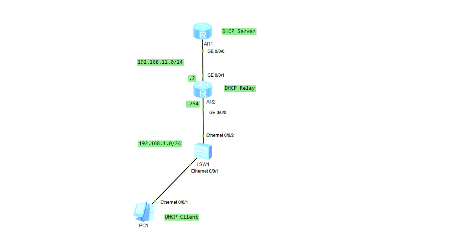
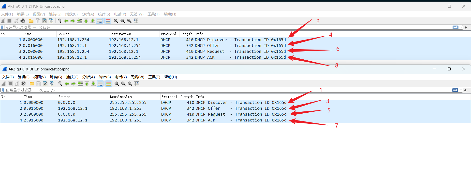
sys sys AR1 dhcp enable int g0/0/0 ip add 192.168.12.1 24 ip pool 1 network 192.168.1.0 mask 24 gateway-list 192.168.1.254 int g0/0/0 dhcp select global ip route-static 192.168.1.0 24 192.168.12.2
sys sys AR2 dhcp enable int g0/0/1 ip add 192.168.12.2 24 int g0/0/0 ip add 192.168.1.254 24 dhcp select relay dhcp relay server-ip 192.168.12.1
Port VLAN是实现VLAN的方式之一,它利用交换机的端口进行VALN的划分,一个端口只能属于一个VLAN。 Tag VLAN是基于交换机端口的另一种类型,主要用于是交换机的相同Vlan内的主机之间可以直接访问,同时对不同Vlan的主机进行隔离。Tag VLAN遵循IEEE802.1Q协议的标准,在使用配置了Tag VLAN的端口进行数据传输时,需要在数据帧内添加4个字节的802.1Q标签信息,用于标示该数据帧属于哪个VLAN,便于对端交换机接收到数据帧后进行准确的过滤。
四、实验设备
PC1,PC2,PC3,PC4
两台S5700交换机
五、实验的步骤和结果
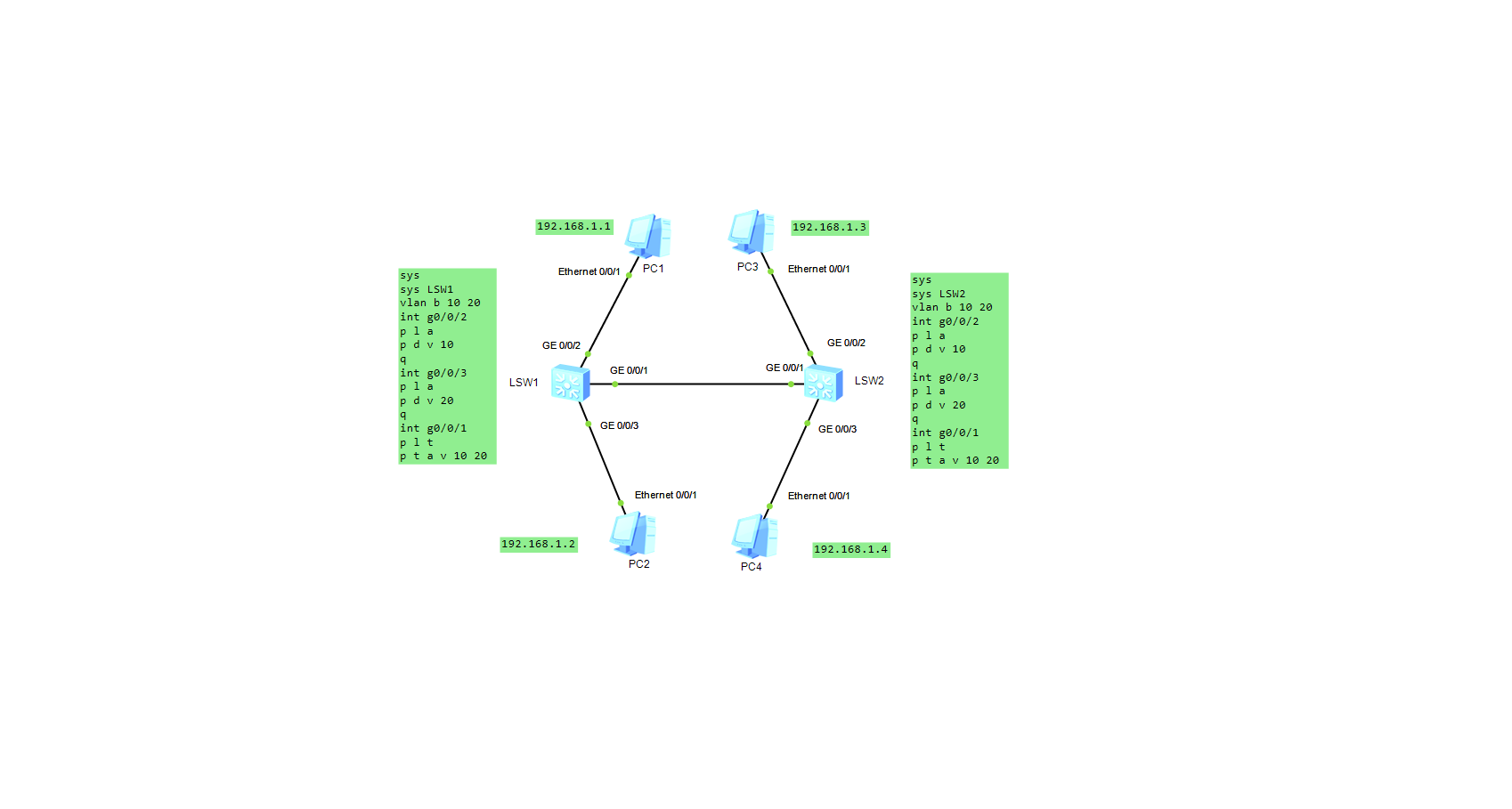
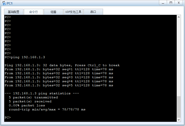
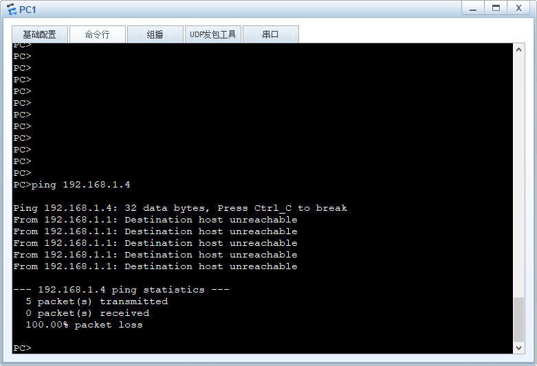
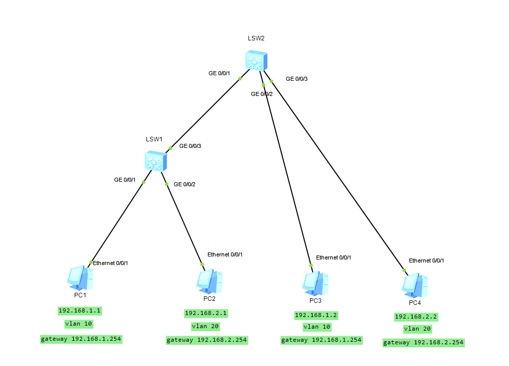
结果就是PC1ping通PC3,PC2ping通PC4,PC1和PC3都不能访问PC2和PC4
1 2 3 4 5 6 7 8 9 10 11 12 13 14 15
# LSW1配置: sys sys LSW1 vlan b 10 20 int g0/0/2 p l a p d v 10 q int g0/0/3 p l a p d v 20 q int g0/0/1 p l t p t a v 10 20
1 2 3 4 5 6 7 8 9 10 11 12 13 14 15
# LSW2配置: sys sys LSW2 vlan b 10 20 int g0/0/2 p l a p d v 10 q int g0/0/3 p l a p d v 20 q int g0/0/1 p l t p t a v 10 20
sys sys LSW1 vlan batch 10 20 int g0/0/1 p l a p d v 10 int vlanif10 ip add 192.168.1.254 24 int g0/0/2 p l a p d v 20 int vlanif20 ip add 192.168.2.254 24
sys sys LSW1 vlan batch 10 20 int g0/0/1 p l a p d v 10 int g0/0/2 p l a p d v 20 int g0/0/3 p l t p t a v 10 20
交换机LSW2配置
1 2 3 4 5 6 7 8 9 10 11 12
sys sys LSW2 vlan batch 10 20 int g0/0/1 p l t p t a v 10 20 int g0/0/2 p l a p d v 10 int g0/0/3 p l a p d v 20
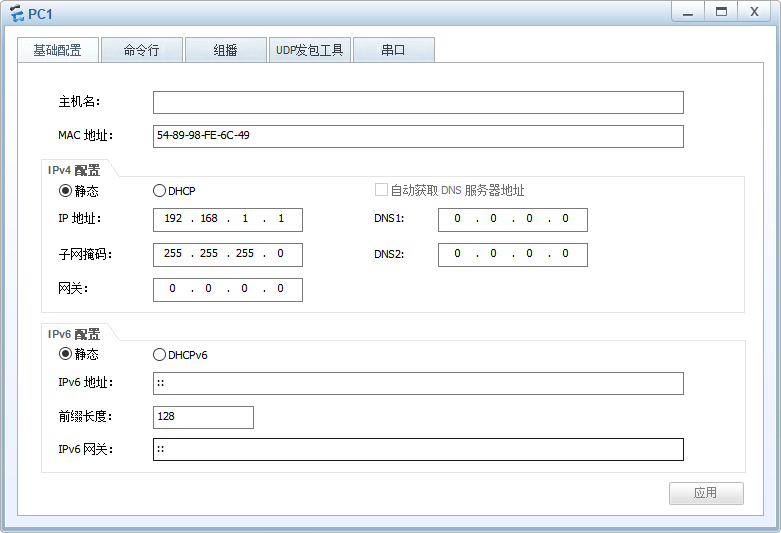
PC1配置
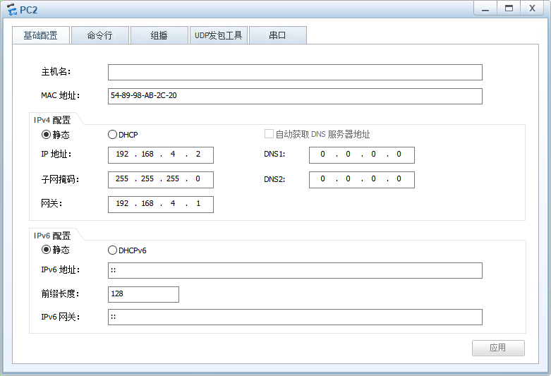
PC2配置
PC3配置
PC4配置
我发现这实验有问题的。。。可能是我技术不好,这个更改后的配置,更改前的配置如下:
交换机LSW2配置(其他配置不变)
1 2 3 4 5 6 7 8 9 10 11 12 13 14 15 16
sys sys LSW2 vlan batch 10 20 int g0/0/1 p l t p t a v 10 20 int g0/0/2 p l a p d v 10 int g0/0/3 p l a p d v 20 int vlanif 10 ip add 192.168.1.254 24 int vlanif 20 ip add 192.168.2.254 24
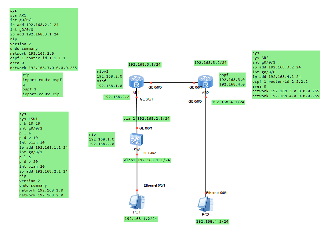
sys sys LSW1 v b 10 20 int g0/0/2 p l a p d v 10 int vlan 10 ip add 192.168.1.1 24 int g0/0/1 p l a p d v 20 int vlan 20 ip add 192.168.2.1 24 rip version 2 undo summary network 192.168.1.0 network 192.168.2.0
AR1配置
1 2 3 4 5 6 7 8 9 10 11 12 13
sys sys AR1 int g0/0/1 ip add 192.168.2.2 24 int g0/0/0 ip add 192.168.3.1 24 rip version 2 undo summary network 192.168.2.0 ospf 1 router-id 1.1.1.1 area 0 network 192.168.3.0 0.0.0.255
AR1路由重分布配置
1 2 3 4 5
rip import-route ospf q ospf 1 import-route rip
AR2配置
1 2 3 4 5 6 7 8 9 10
sys sys AR2 int g0/0/1 ip add 192.168.3.2 24 int g0/0/0 ip add 192.168.4.1 24 ospf 1 router-id 2.2.2.2 area 0 network 192.168.3.0 0.0.0.255 network 192.168.4.0 0.0.0.255
PC配置
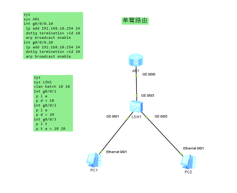
单臂路由
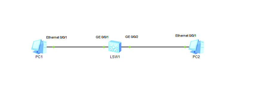
一、实验设备
PC1,PC2
一台S5700交换机和一台AR2220交换机
二、实验的步骤和结果
交换机配置
1 2 3 4 5 6 7 8 9 10 11 12
sys sys LSW1 vlan batch 10 20 int g0/0/1 p l a p d v 10 int g0/0/2 p l a p d v 20 int g0/0/3 p l t p t a v 10 20
路由器配置
1 2 3 4 5 6 7 8 9 10
sys sys AR1 int g0/0/0.10 #创建子接口 ip add 192.168.10.254 24 dot1q termination vid 10 #配置子接口终结的VLAN ID arp broadcast enable#开启子接口的arp广播功能 int g0/0/0.20 ip add 192.168.20.254 24 dot1q termination vid 20 arp broadcast enable
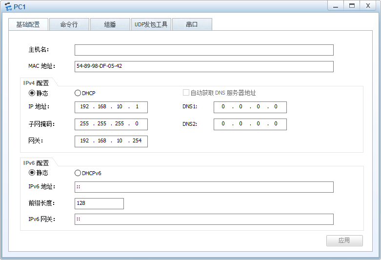
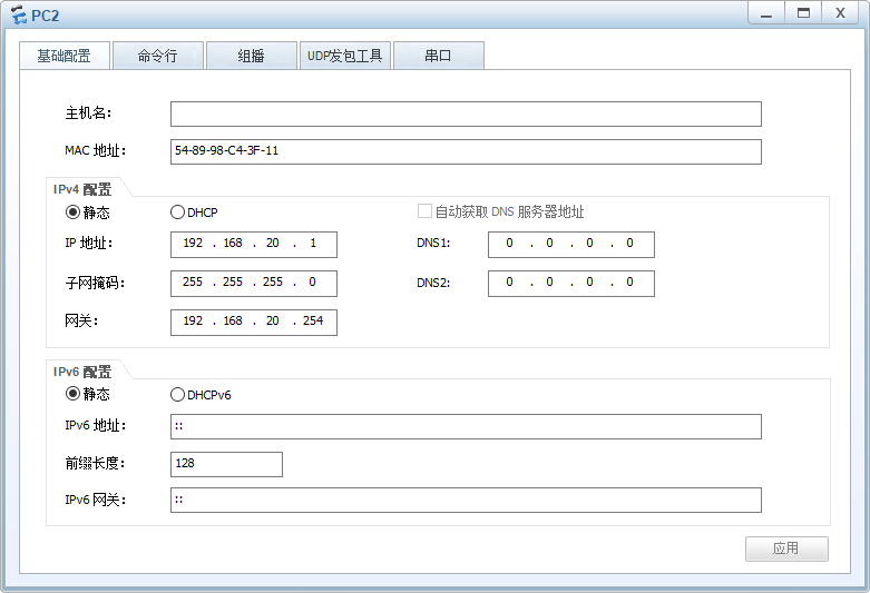
PC配置
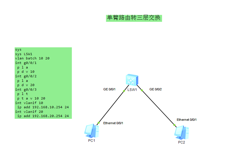
单臂路由转三层交换
一、实验设备
PC1,PC2
一台S5700交换机
二、实验的步骤和结果
交换机配置
1 2 3 4 5 6 7 8 9 10 11 12 13 14 15 16
sys sys LSW1 vlan batch 10 20 int g0/0/1 p l a p d v 10 int g0/0/2 p l a p d v 20 int g0/0/3 p l t p t a v 10 20 int vlanif 10 ip add 192.168.10.254 24 int vlanif 20 ip add 192.168.20.254 24
# 在跟目录下放置www目录,然后内置两个目录,分别是www目录和void目录
# 写入不同的html页面
[root@localhost /]# cd www
[root@localhost www]# ls
void  www
[root@localhost www]# cat void/index.html
this is void web site...
[root@localhost www]# cat www/index.html
this is www web site...
[root@localhost www]#


.png)
.png)
.png)
.png)
.png)
.png)
.png)
.png)
.png)
.png)
.png)
.png)
.png)

.png)
.png)
.png)
.png)
.png)